

Product Description and ApplicationProducts description and application
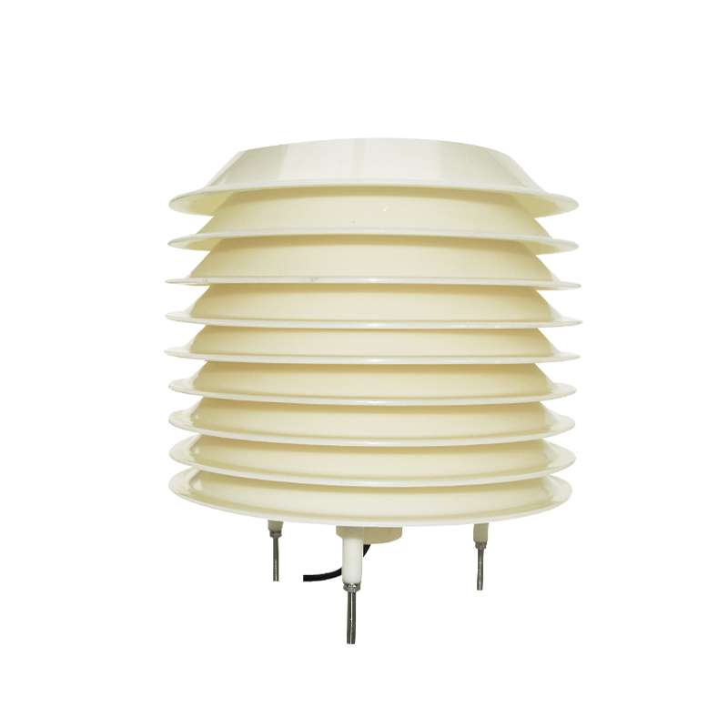
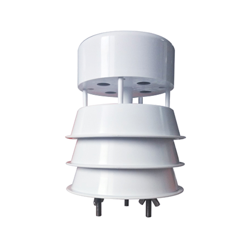
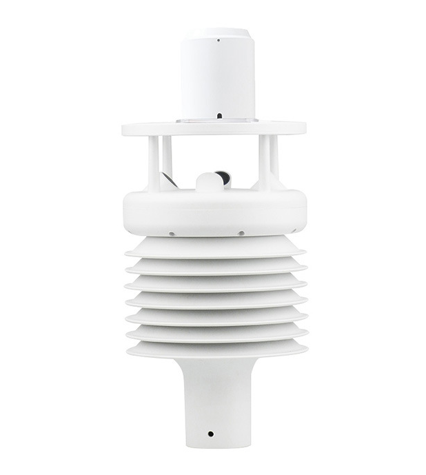
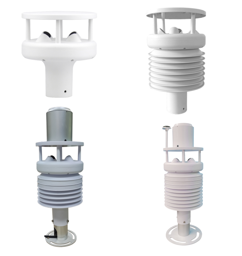
The ultrasonic environmental monitor is a maintenance-free ultrasonic environmental monitoring sensor. Compared with traditional mechanical anemometers, it has no inertia effect of rotating parts and can quickly and accurately measure more than 10 environmental meteorological elements. It can be equipped with an efficient heating device to ensure reliable operation in severe cold environments. It is suitable for monitoring wind speed and other environmental elements in the fields of agriculture, meteorology, forestry, electricity, environmental protection, ports, railways, highways, etc.
FeaturesFeatures
ØIt adopts the time difference measurement principle and has strong resistance to environmental interference.
ØAdopts efficient filtering algorithm and special compensation technology for rainy and foggy weather.
ØUse more expensive and accurate 200Khz ultrasonic probe to ensure more accurate and stable measurement of wind speed and direction .
ØThe salt spray corrosion resistant probe is selected with a fully sealed structure . It has passed the national standard salt spray test and has good results . It is suitable for coastal , port and other environments.
ØRS232/RS485/4-20mA/0-5V , or 4G wireless signal and other output modes are optional.
ØModular design, high integration , you can select any environmental monitoring elements as needed, up to more than 10 elements can be integrated.
ØThe product has wide environmental adaptability and has undergone rigorous environmental tests such as high and low temperature, waterproof, salt spray, sand and dust, etc.
ØLow power consumption design.
ØOptional functions include heating, GPS/ Beidou positioning, electronic compass, etc。
The main technical parametersGeneral Specifications | |||
Electrical parameters | Mechanical structure parameters | ||
Operating Voltage | DC 9V -30V or 5V | Material | ABS engineering plastics |
Product Power | 0.4W ( 10.5W when heating ) | Working environment humidity | 0~100%RH |
Signal output mode | 4~20mA/ 0-5V | Working temperature | -40 ℃ ~ +60 ℃ |
RS485 or 4G wireless signal output | Protection level | IP65 | |
Outlet mode | Aviation socket | ||
Exterior color | milky | ||
reference weight | About 0.5KG (2 parameters ); 1KG (5 parameters or more parameters ) | ||
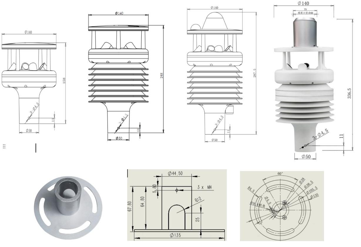
Mounting dimensions
Dimensions in millimeters
Two parameters (CC-M70)Multiple parameters(CC-M71,CC-M72,CC-M73)
Sensor Technical Specifications
Optional environmental factors | Range | Accuracy | Resolution | Power consumption |
Wind speed | 0-70m/s | Starting wind speed ≤ 0.8m/s , ± (0.5+0.02V)m/s ; | 0.01m/s | 0.1W |
wind direction | 0 ~ 360 | ± 2° | 1 ° | |
Atmospheric temperature | -40~100 ℃ | ± 0.3 ℃ | 0.1 ℃ | 1mW |
Atmospheric humidity | 0~100%RH | ± 3%RH | 0.1%RH | |
Atmospheric pressure | 300~1100hPa | ± 1 hPa ( 25 °C) | 0.1 hPa | 0.1mW |
Rainfall Accumulation ( Optical Rainfall ) | Measuring range: 0--4mm/min | ± 10% (Indoor static test, rain intensity is 2mm/min ) | 0.1mm | 240mW |
Illuminance | 0-200000Lux (outdoor) | ± 3% | 1 Lux | 0.1mW |
radiation | 0-1500 W/ m2 | ± 2% | 1 W/m 2 | 400mW |
CO2 | 0~5000ppm | ± (50ppm+5%) | 1ppm | 100mW |
noise | 30~130dB(A) | ± 1dB(A) | 0.1 dB(A) | |
PM2.5/10 | 0-500 μg /m3 | Accuracy: ≤ 100ug/m3 : ± 10ug/m3 ; > 100ug/m3 : ± 10% reading ( calibrated with TSI 8530 , 25 ± 2 ℃, 50 ± 10%RH environmental conditions) | 1 μg /m3 | 0.5W |
PM100 | 0-20000ug/m3 | ±30ug/m3±20% | 1 μg /m3 | 0.5W |
Four gases ( CO , NO2 , SO2 , O3 ) | CO ( 0-1000ppm ) NO2 ( 0-20ppm ) SO2 ( 0-20ppm ) O3 ( 0-10ppm ) | ≤ ± 3% of reading ( 25 °C) | CO ( 0.1ppm ) NO2 ( 0.01ppm ) SO2 ( 0.01ppm ) O3 ( 0.01ppm ) | 0.2W |
Electronic compass | 0 ~ 360 | ± 3° | 1 ° | 100mW |
GPS | longitude ( -180~180 °) latitude ( -90~90 °) Altitude ( -3276.7~3276.7m ) | ≤ 10m ≤ 10m ≤ 3 m | 0.1 seconds 0.1 seconds 0.1m | |
Total power consumption = optional sensor power consumption + mainboard basic power consumption | Mainboard basic power consumption | 300mW | ||
Wiring diagram
485 or 232 signal output, there is a 4 -pin aviation plug at the bottom of the sensor, and the pins corresponding to the pins are defined as follows:
1—— Power supply positive VCC (red)
2—— Power negative GND (green)
3——485A+ (black)
4——485B- (yellow)
When the analog signal output is 4-20mA or 0-5V , the functional definition relationship between the sensor elements and the line colors can be found on the product label.
Note: Make sure the wiring is correct before supplying power.


Long press the screen to identify the QR code
Open the phone to scan QR code