| Overview |
This instrument is a primary instrument for measuring precipitation, and its performance meets the requirements of the national standard GB / T 21978.2-2014 "Tipping Bucket Rain Gauge".
The core component of this instrument, the tipping bucket, adopts a three-dimensional streamlined design, which makes the tipping bucket turn over water more smoothly and easy to clean.
This instrument is a precision rain gauge. During use, the tipping bucket and the water outlet of the water diversion funnel must be regularly maintained and cleaned.
The inclination angle of the bucket of this instrument has been adjusted and locked at the optimal inclination position when it leaves the factory. When installing the instrument, you only need to install the bucket and adjust the base level according to the requirements of this manual before putting it into use .
The tipping bucket rain gauge is a hydrological and meteorological instrument used to measure rainfall in nature and convert rainfall into digital information output in the form of switch quantity to meet the needs of information transmission, processing, recording and display.
| Features |
(1) The resolution is available in three options : 0.1mm / 0.2mm / 0.5mm .
( 2 ) High precision and good stability .
(3) The dump truck parts are well-made with small friction torque, so the parts can flip sensitively, have stable performance and work reliably .
(4) The overall structure is made of 304 stainless steel, which has strong anti-rust ability and good appearance quality . The rain inlet is made of 304 stainless steel shell punched and drawn as a whole, with high smoothness and small error caused by water stagnation .
( 5 ) A protective mesh is built into the rain inlet to prevent fallen leaves, mosquitoes and other insects from blocking the rain outlet.
( 6 ) There is a level adjustment bubble inside the chassis to assist in adjusting the levelness of the equipment at the bottom angle.
( 7 ) It has a clock circuit that can query the contents of up to 10 registers.
| Scope of application |
The rain gauges independently developed and produced by our company are used to measure precipitation, precipitation intensity, precipitation time, etc. They can be used in meteorological stations , hydrological stations , agriculture and forestry, national defense, field monitoring stations and other relevant departments, and can provide original data for flood control, water supply scheduling, and water situation management of power stations and reservoirs.
| Technical Parameters |
Rain collector materials:Brass,other part is SS304
Rain-bearing diameter : φ200mm ; sharp angle of cutting edge: 40 ° ~ 45 °
Range: Default 0~100mm / day (can be modified to any range within 6553.5 mm/ day )
point Identify Force : 0.1mm / 0.2mm /0.5mm
Rain intensity range: 0.01mm ~ 4mm/min (maximum rainfall intensity allowed is 8mm/min )
allow Yes Degree: ≤± 3%
Output signal: A : voltage signal ( 0 ~ 2V , 0 ~ 5V , 0 ~ 10V , choose one)
B : 4 ~ 20mA (current loop)
C : RS485 (standard Modbus-RTU protocol, device default address: 01 )
D: Pulse signal (one pulse represents 0.1mm / 0.2mm / 0.5mm rainfall)
Supply voltage: 5 ~ 24V DC (when output signal is 0 ~ 2V , RS485 )
Heating version: 200~220VAC
12 ~ 24V DC (when the output signal is 0 ~ 5V , 0 ~ 10V , 4 ~ 20mA )
Power: ≤0.2W , heating power ≤ 100 W
Working environment: Temperature: 0 ℃ ~ 50 ℃ ; Humidity : < 95 % RH
Auto heating control:set start temperature heating -15-10C
Set top temperature heating 10-30C
(can be setting before shipment or you can set any value by RS485 command)
| Form Factor |
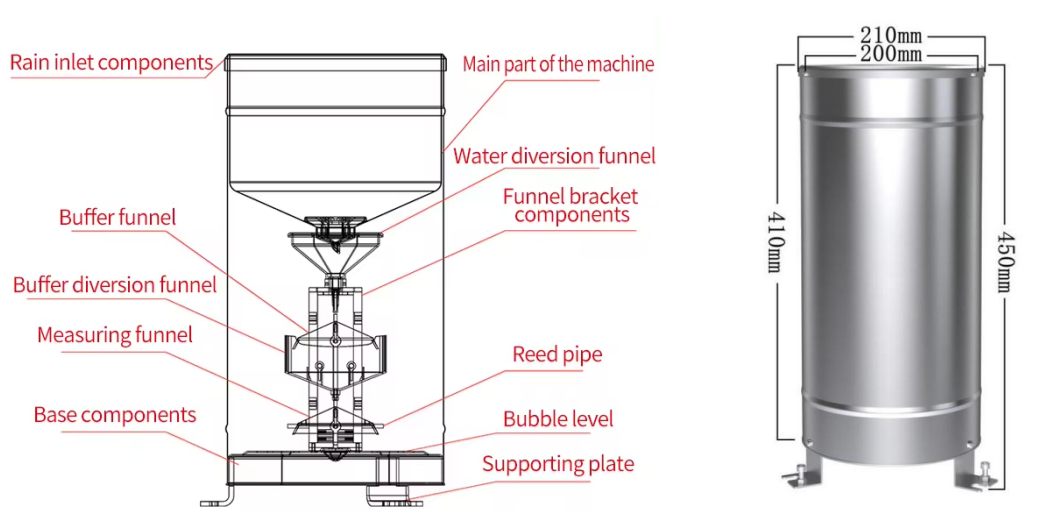
6 | Wiring method |
The tipping bucket rain gauge can be connected to various data acquisition devices with differential input, data acquisition cards, remote data acquisition modules and other equipment . The wiring instructions are as follows :
Power cord: three-core sheathed wire, brown: live wire, blue: neutral wire, yellow-green: ground wire
Signal line: two-core twisted pair sheathed line, yellow: 485A green: 485B
7 | Data conversion methods |
the tipping bucket rain gauge is to calculate the cumulative rainfall so far starting from zero o'clock (00:00) of the day. The default range is 0 to 100mm , and other ranges can also be selected.
H: rainfall, unit: mm;
V : the voltage value collected by the collector, unit: V ;
A : The current value collected by the collector, unit: mA ;
output signal | Data conversion methods for each range | ||
0 ~ 50mm | 0 ~ 100mm | 0 ~ 200mm | |
0~2V DC | H= 25 *V | H= 50*V | H= 10 0*V |
0~5V DC | H= 1 0*V | H= 20*V | H= 4 0*V |
0~10V DC | H= 5 *V | H= 10*V | H= 2 0*V |
4~20mA | H= 3 . 1 25*A - 1 2 . 5 | H= 6.25*A - 25 | H= 12.5 *A - 50 |
pulse | One pulse represents 0.1mm / 0.2mm / 0.5mm rainfall | ||
RS485 signal (default address 01 ):
Standard Modbus-RTU protocol, baud rate: 9600 ; check bit: none; data bit: 8 ; stop bit: 1
7.1 Modify address
For example: Change the address of the sensor with address 1 to 2 , master → slave
Original address | function code | Register address high | Register Address Low | Start address high | Start address low | CRC16 Low | CRC16 High |
0X01 | 0X06 | 0X00 | 0X30 | 0X00 | 0X02 | 0X08 | 0X04 |
If the sensor receives the data correctly, the data is returned along the original route .
Note: If you forget the original address of the sensor, you can use the broadcast address 0 XFE instead . When using 0 XFE , the host can only connect to one slave , and the returned address is still the original address, which can be used as a method for address query.
7.2 Query/ Set Time
Query time, master → slave
Original address | function code | Register address high | Register Address Low | High register length | Low register length | CRC16 Low | CRC16 High |
0X01 | 0X03 | 0X00 | 0X34 | 0X00 | 0X03 | 0X44 | 0X05 |
If the sensor receives correctly, the following data will be returned, slave → host
address | function code | Data length | Year | moon | day | hour | point | Second | CRC16 Low | CRC16 High | |
0X01 | 0X03 | 0X06 | 0X20 | 0X03 | 0X30 | 0X10 | 0X25 | 0X10 | 0X77 | 0X8C | |
|
|
| BCD code, indicating: 10:25:10 on March 30, 2020 |
|
| ||||||
If the clock is deviated, you can calibrate the clock, master → slave
address | 0X01 | |
function code | 0X10 | |
Start register address high | 0X00 | |
Start register address low | 0X34 | |
High register length | 0X00 | |
Low register length | 0X03 | |
Data length | 0X06 | |
Year | 0X20 | BCD code Meaning: 2020-04-03 17:06:28 |
moon | 0X04 | |
day | 0X03 | |
hour | 0X17 | |
point | 0X06 | |
Second | 0X28 | |
CRC16 Low | 0XE2 | |
CRC16 High | 0XF4 |
If the sensor receives correctly, it returns the following data, slave → host
address | function code | Start register address high | Start register address low | High register length | Low register length | CRC16 Low | CRC16 High |
0X01 | 0X10 | 0X00 | 0X34 | 0X00 | 0X03 | 0XC1 | 0XC6 |
7.3 Contoller Box install
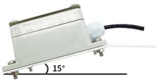
15 degree installation with flat plate
7.4 Controller box temp and snow/rain requiry
address | function code | register High address | register Address low | register Data High | Register data low | CRC16 Low | CRC16 High |
0 X 01 | 0 X 03 | 0X00 | 0X 00 | 0x0 0 | 0X 02 | 0 XC4 | 0 X0B |
If the sensor receives correctly, the following data will be returned, slave → host
address | function code | Data length | Register 0 data high | Register 0 data low | Register 1 data high | Register 1 data low | CRC16 Low | CRC16 High |
0 X 0 1 | 0 X 03 | 0 X 0 4 | 0x0 0 | 0X0A | 0X00 | 0X1C | 0 XFA | 0x55 |
0A no rain/snow fall 0B rain/snow fall | Rain gauge Moment temperature : 28.0℃ | |||||||
7.5Set temperature
Taking the setting of the startup temperature to 4℃as an example, the master → slave
address | function code | register High address | register Address low | register Data High | Register data low | CRC16 Low | CRC16 High |
0 X 01 | 0 X 06 | 0X00 | 0X 5F | 0x0 0 | 0X 28 | 0 XB9 | 0 XC6 |
If the sensor receives the data correctly, the data is returned along the original route .
Take the setting of stop temperature 15 ℃ as an example, master → slave
address | function code | register High address | register Address low | register Data High | Register data low | CRC16 Low | CRC16 High |
0 X 01 | 0 X 06 | 0X00 | 0X 60 | 0X00 | 0X 96 | 0 x09 | 0 XBA |
If the sensor receives the data correctly, the data is returned along the original route .
7.6 Query start/stop heating temperature data
Query the data of the sensor (address 1) ( start heating temperature, stop heating temperature), host → slave
address | function code | Start register address high | Start register address low | High register length | Low register length | CRC16 Low | CRC16 High |
0 X 0 1 | 0 X 03 | 0x00 | 0 X 5F | 0X00 | 0 X 0 2 | 0 XF4 | 0 x19 |
If the sensor receives correctly, the following data will be returned, slave → host
address | function code | Data length | Register 0 data high | Register 0 data low | Register 1 data high | Register 1 data low | CRC16 Low | CRC16 High |
0 X 0 1 | 0 X 03 | 0 X 0 4 | 0x0 0 | 0X2 8 | 0X00 | 0X 96 | 0 XFA | 0x55 |
Start-heating temperature : 4 ℃ | Stop-heating temperature : 1 5 ℃ | |||||||
8 | Installation and Adjustment |
8.1 Unpacking and Inspection
① Carefully read the product manual and check whether the equipment accessories are complete by checking the packing list.
② Check whether the appearance of the instrument is damaged, pay special attention to avoid damaging the tip of the bucket shaft and the water diversion tips at both ends of the bucket, and do not touch the inner wall of the bucket with your fingers to stain the bucket.
8.2 Fabrication and installation of cement platform
When installing on the ground or roof outdoors, a cement platform should be made first. The height of the cement platform above the ground is 22cm , and the dimensions are: 40cm long x 40cm wide , and the upper plane is a horizontal plane. When installing on the ground, the height of the rain outlet should be 70cm from the ground .
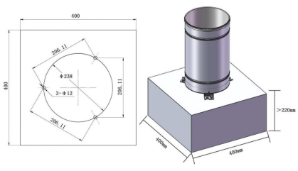
8.3 Install and fix the instrument and adjust the bracket level
three installation holes with a diameter of Φ12mm and a depth of 8 to 10cm on the cement platform . The installation holes are located on the circumference of Φ238mm and are evenly divided at 120 degrees . Insert the cable into the instrument base and prepare to install and fix the instrument. Remove the outer tube of the instrument, place the expansion bolts in the installation holes, install the instrument base on the three expansion bolts, use the leveling bolts to adjust the level of the instrument base so that the level bubble is in the center circle, fix the leveling bolts, and then tighten the nuts to lock the three legs. Finally, install the outer tube of the instrument and lock the expansion bolts, and the instrument can be put into use.
8.4 Rain gauge mounting bracket is optional, suitable for outdoor clamp installation
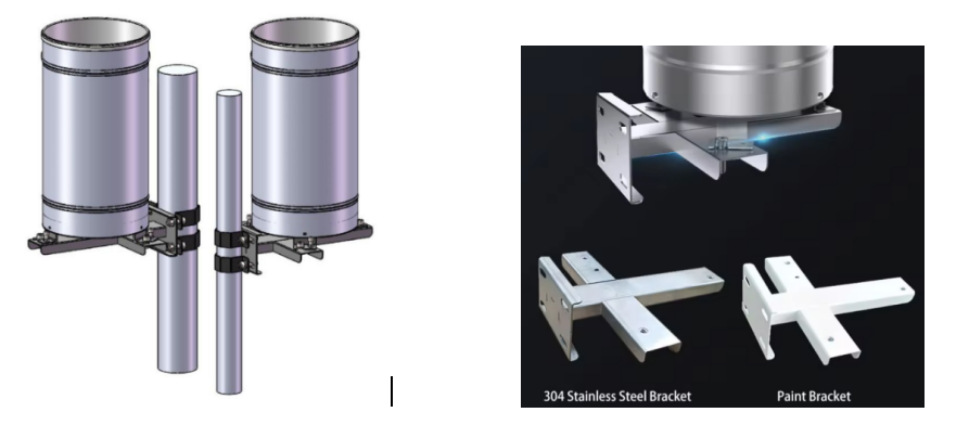
9 | Fault phenomenon and troubleshooting |
This table lists the common fault phenomena, causes and troubleshooting methods that may occur on the instrument.
Central station performance | Rain sensor failure | Solution |
No data is received during rainfall | ① Reed switch failure ②The distance between the magnet and the reed switch is too far ③The welding wire falls off or the signal line is broken ④The dump box is stuck ⑤ Instrument blockage | ①Replace the reed switch ②Adjust the distance of the reed switch ③Repair ④ Exclusion ⑤ Clear the blockage |
The rainfall data received during rainfall is quite different from the rainfall gauge. | ① The tilt angle of the rain sensor bucket is out of adjustment, but this error generally does not exceed ± 10% ② The magnet and the reed switch are not in the right position, which results in intermittent operation and partial signal loss. ③ The rain gauge is far away from the system rain sensor or there is strong wind. | ①Re -titrate and adjust the inclination ②Adjust the distance ③Objective reasons, not instrument failure |
The rainfall figures keep coming, but it doesn't actually rain. | Check if the socket is soaked in water, which often happens after heavy rain. | Deal with water ingress and reinstall |
Note: The fault phenomena listed in the table are not necessarily faults of the rain gauge itself. After checking the instrument itself and eliminating the faults, you should also check whether there are faults in the instrument transmission line, data acquisition device, telemetry terminal and other equipment, and eliminate and solve them one by one.
| Product Warranty |
from the date of delivery , if the fault is caused by sensor quality problems (not man-made damage), our company will be responsible for free repair or replacement. After the warranty period, only the cost will be charged.
Download:
