CC-M15-C Wind speed and direction all in one Product Manual
| Introduction |
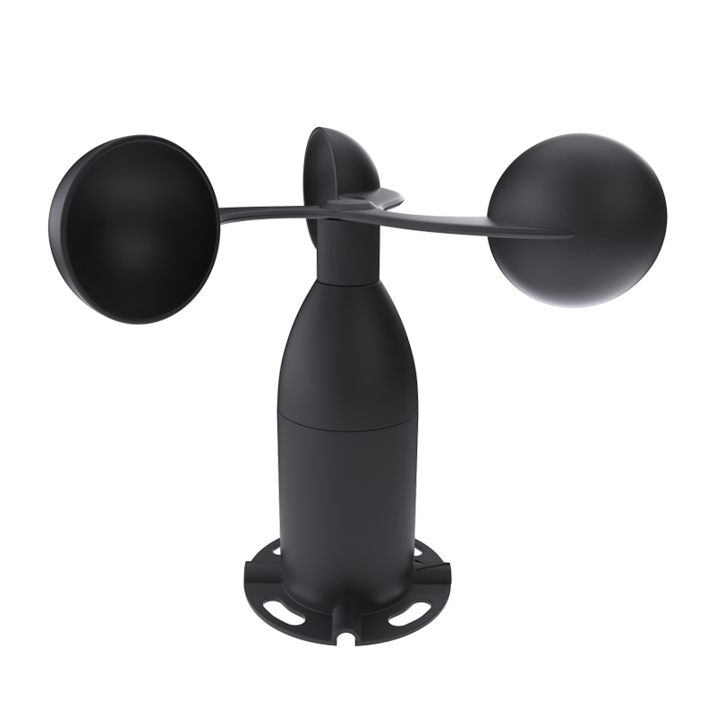
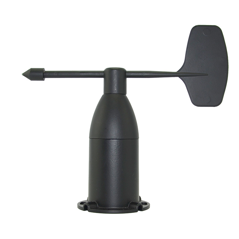
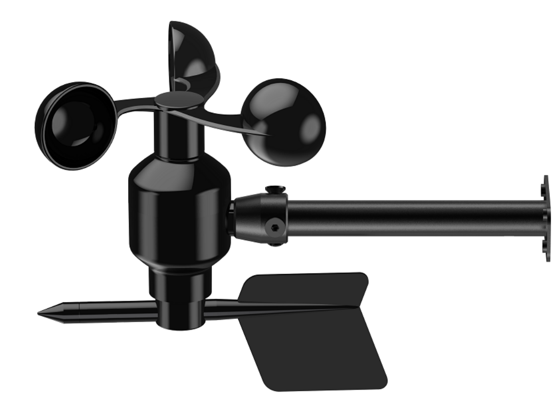
Integrated wind speed and direction sensor is a wind speed and direction measuring instrument independently developed and produced by our company. The sensor shell is made of polycarbonate composite material, which has good anti-corrosion characteristics, which can ensure long-term use of the sensor without rust. At the same time, it cooperates with the internal smooth bearing system to ensure the stability of information collection. Internal integration of photoelectric conversion mechanism, industrial microcomputer processor, standard current generator, current driver, etc.
The circuit is designed according to EMI specifications, making the whole with extremely reliable anti-electromagnetic interference ability, and the electronic components are imported industrial-grade chips to ensure the stability of the measurement parameters and electrical performance.
| Characteristics |
(1) It adopts an integrated design, which is small in size and easy to install.
(2) High measurement accuracy, fast response speed and good interchangeability.
(3) Realize low cost, low price and high performance.
(4) High data transmission efficiency and reliable performance to ensure normal work.
(5) The power supply has a wide range of adaptation, good data information linearity, and long signal transmission distance.
| Application |
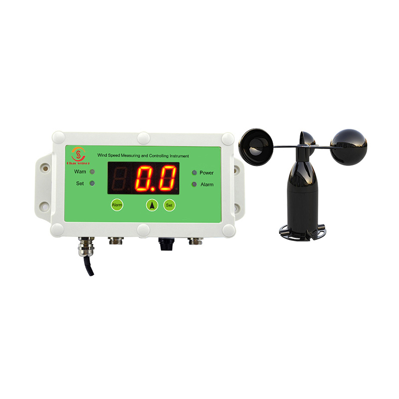
This product is widely used in construction machinery, railway, port, wharf, power plant, meteorology, ropeway, environment, greenhouse, breeding and other fields for measuring wind speed and wind direction.
| Product Information |
4.1 Technical Parameters
Wind Speed Measurement Range: 0-30m/s; 0-50m/s; 0-60m/s; (Other ranges can also be customized)
Wind Direction Measurement Range: 8 Directions
Starting Wind Speed: ≤0.3m/s
Accuracy: ±(0.3+0.03V) m/s, ±1°
Output Signal: A: Voltage signal (Choose one of 0-2V, 0-5V, 0-10V)
B: 4-20mA (Current loop)
C: RS485 (Standard Modbus-RTU protocol, device default
address: 01)
D: SDI-12 (American Hydrological Organization Serial Data
Communication Interface Protocol)
Sensor Supply Voltage (red and black lines):
5-24V DC (When the output signal is 0~2V, RS485, Pulse signal, SDI-12)
12-24V DC (When the output signal is 0-5V, 0-10V, 4-20mA)
Heating Power Supply Voltage (brown and white line): 12-24V DC
Heating Power: Average: 160mA@12V; 310mA@24V
Stability Time: <1 second
Response Time: <1 second
Working Environment: Temperature: 0~50°C; Humidity: <95%RH
Storage Environment: Temperature: 0~50°C; Humidity: <95%RH
4.2 Impedance Requirement of Current Signal
Power Supply Voltage | 9V | 12V | 20V | 24V |
Maximum Impedance | <250Ω | <400Ω | <500Ω | <900Ω |
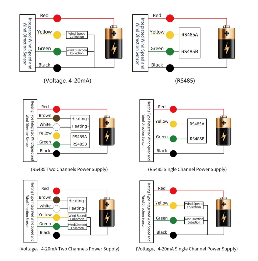
| Using Method |
Integrated Wind Speed and Wind Direction Sensor can be connected to various data collectors with differential inputs, data acquisition cards, remote data acquisition modules and other equipment. The wiring instructions are as follows:
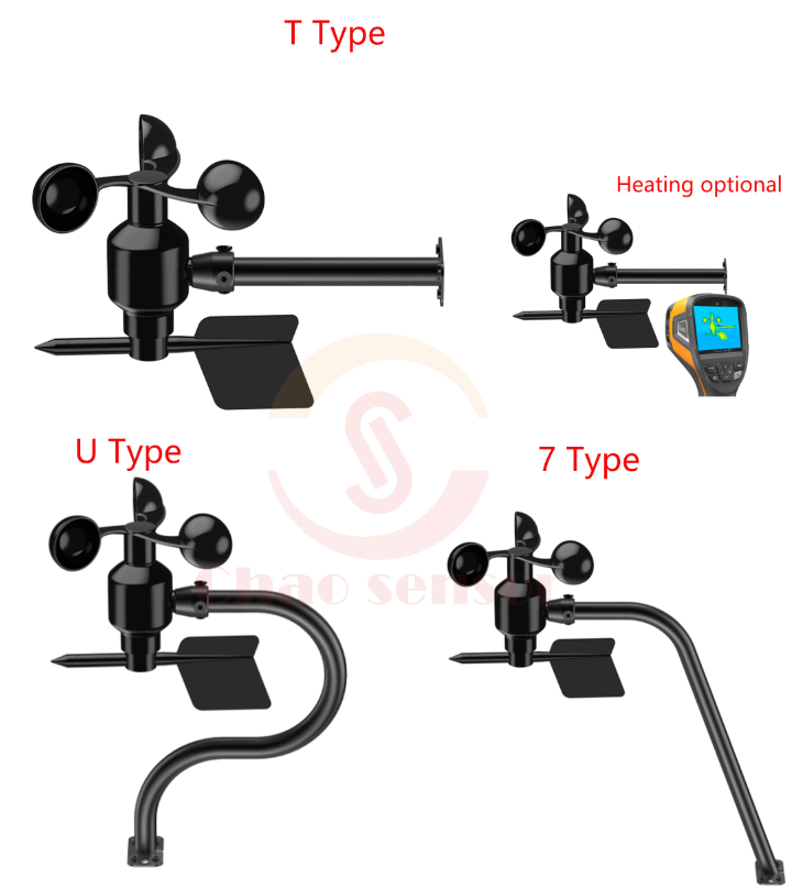
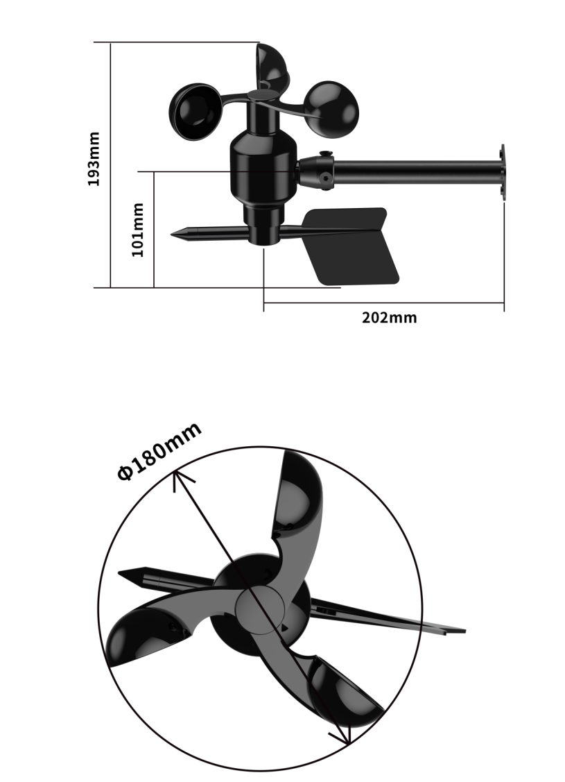
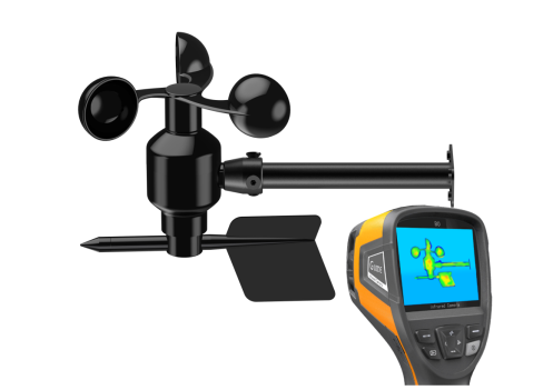
| Form Factor |
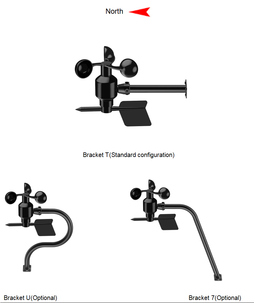
7 | Installation |
Integrated Wind Speed and Wind Direction Sensor (wire outlet points south, the opposite direction is north), the installation method is as below:
8 | Data Conversion Method |
V: voltage value collected by the collector, unit: V;
A: The current value collected by the collector, unit: mA;
Output Signal | Data Conversion Method for Each Range of Wind Speed | |
0~30m/s | 0~60m/s | |
0~2V DC | Wind speed=15*V | Wind speed=30*V |
0~5V DC | Wind speed=6*V | Wind speed=12*V |
0~10V DC | Wind speed=3*V | Wind speed=6*V |
4~20mA | Wind speed=1.875*A-7.5 | Wind speed=3.75*A-15 |
Pulse(NPN or PNP) | One pulse in one second means 0.1m/s | |
0~2V | 0~5V | 0~10V | 4~20mA | RS485 | ||
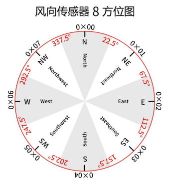
North | 0V | 0V | 0V | 4mA | 0° | 0X00 |
Northeast | 0.25V | 0.625V | 1.25V | 6mA | 45° | 0X01 |
East | 0.5V | 1.25V | 2.5V | 8mA | 90° | 0X02 |
Southeast | 0.75V | 1.875V | 3.75V | 10mA | 135° | 0X03 |
South | 1V | 2.5V | 5V | 12mA | 180° | 0X04 |
Southwest | 1.25V | 3.125V | 6.25V | 14mA | 225° | 0X05 |
West | 1.5V | 3.75V | 7.5V | 16mA | 270° | 0X06 |
Northwest | 1.75V | 4.375V | 8.75V | 18mA | 315° | 0X07 |
RS485 signal(default address 01):
Standard Modbus-RTU protocol,
baud rate: 9600; check bit: no; data bit: 8; stop bit: 1
8.1 Modification Address
For example: change the address of the sensor with address 1 to 2, master→slave
Original Address | Function Code | Start Register High | Start Register Low | Start Address High | Start Address Low | CRC16 Low | CRC16 High |
0X01 | 0X06 | 0X00 | 0X30 | 0X00 | 0X02 | 0X08 | 0X04 |
If the sensor receives correctly, the data will be returned in the same way.
Note: If you forget the original address of the sensor, you can use the broadcast address 0XFE instead. When using 0XFE, the host can only connect to one slave, and the return address is still the original address, which can be used as a method for address query.
8.2 Query Data
Query the data (wind speed, wind scale, wind angle, wind direction) of the sensor (address 1), host→slave
Address | Function Code | Start Register Address High | Start Register Address Low | Register Length High | Register Length Low | CRC16 Low | CRC16 High |
0X01 | 0X03 | 0X00 | 0X00 | 0X00 | 0X04 | 0X44 | 0X09 |
If the sensor receives correctly, the following data will be returned, slave→host.
Address | 0X01 | |
Function Code | 0X03 | |
Data Length | 0X08 | |
Register 0 Data High | 0X00 | Wind Speed: 3.6m/s |
Register 0 Data Low | 0X24 | |
Register 1 Data High | 0X00 | Wind Scale: Level 3 |
Register 1 Data Low | 0X03 | |
Register 2 Data High | 0X05 | Wind Direction Angle: 135.0° |
Register 2 Data Low | 0X46 | |
Register 3 Data High | 0X00 | Wind Direction:Southeast |
Register 3 Data Low | 0X03 | |
CRC16Low | 0X14 | |
CRC16High | 0XCD |
Attention: If you have bought the product with heating fuction, the protocol is as below:
8.3Setting Temperature
Take setting the stop temperature at 30°C as an example, host→slave
Address | Function Code | Register Address High | Register Address Low | Register Data High | Register Data Low | CRC16Low | CRC16High |
0X01 | 0X06 | 0X00 | 0X6C | 0X01 | 0X2C | 0X49 | 0X9A |
If the sensor receives correctly, the data will be returned in the same way.
Take setting the start temperature at 5°C as an example, host→slave
Address | Function Code | Register Address High | Register Address Low | Register Data High | Register Data Low | CRC16Low | CRC16High |
0X01 | 0X06 | 0X00 | 0X6D | 0X00 | 0X32 | 0X99 | 0XC2 |
If the sensor receives correctly, the data will be returned in the same way.
8.4Query the Start/Stop Heating Temperature Data
Query the data (stop heating temperature, start heating temperature) of the sensor (address 1), host→slave
Address | Function Code | Start Register Address High | Start Register Address Low | Register Length High | Register Length Low | CRC16 Low | CRC16 High |
0X01 | 0X03 | 0X00 | 0X6C | 0X00 | 0X02 | 0X04 | 0X16 |
If the sensor receives correctly, the following data will be returned, slave→host.
Address | Function Code | Data Length | Register 0 Data High | Register 0 Data Low | Register 1 Data High | Register 1 Data Low | CRC16Low | CRC16High |
0X01 | 0X03 | 0X04 | 0X01 | 0X2C | 0X00 | 0X32 | 0XBB | 0XD3 |
Stop Heating Temperature: 30°C | Start Heating Temperature: 5°C | |||||||
| Wind Direction 8Azimuth Map |
10 | Wind Scale Sheet |
Wind Scale | Name of Wind | Wind Speed (m/s) | (km/h) | Land Phenomenon | Sea State |
0 | No wind | 0-0.2 | <1 | Quiet, smoke straight up | Calm as a mirror |
1 | Light air | 0.3-1.5 | 1-5 | The smoke can indicate the direction of the wind, but the wind vane cannot turn. | Tiny waves |
2 | Light air | 1.6-3.3 | 6-11 | The human face feels windy, the leaves make a slight noise, and the weather Vanecan turn. | Wavelet |
3 | Breeze | 3.4-5.4 | 12-19 | The leaves and twigs swayed endlessly, and the flag unfolded. | Wavelet |
4 | Soft breeze | 5.5-7.9 | 20-28 | Can blow up dust and paper on the ground, and the twigs of the tree move slightly. | Slight sea |
5 | Fresh breeze | 8.0-10.7 | 29-38 | The leafy twigs sway, and the inland water has wavelets. | Moderate sea |
6 | Strong breeze | 10.8-13.8 | 39-49 | Big branches swing, electric wires whirring, difficult to lift umbrellas. | Rough sea |
7 | Strong wind | 13.9-17.1 | 50-61 | The whole tree is swaying, it is inconvenient to walk in the wind. | Surge |
8 | Gale | 17.2-20.7 | 62-74 | The twigs are broken, and people feel a lot of resistance to move forward. | Fierce waves |
9 | Strong gale | 20.8-24.4 | 75-88 | The building is damaged (the top of the chimney and the roof tiles move). | Violent waves |
10 | Whole gale | 24.5-28.4 | 89-102 | Rare on land, trees can be uprooted when seen, causing serious damage to buildings. | Violent waves |
11 | Storm wind | 28.5-32.6 | 103-117 | Rare on land, trees can be uprooted when seen, causing serious damage to buildings. | Special Phenomenon |
12 | Hurricane | 32.7-36.9 | 118-133 | Very few on land, its destructive power is extremely high. | Special Phenomenon |
13 | Hurricane | 37.0-41.4 | 134-149 | Very few on land, its destructive power is extremely high. | Special Phenomenon |
14 | Hurricane | 41.5-46.1 | 150-166 | Very few on land, its destructive power is extremely high. | Special Phenomenon |
15 | Hurricane | 46.2-50.9 | 167-183 | Very few on land, its destructive power is extremely high. | Special Phenomenon |
16 | Hurricane | 51.0-56.0 | 184-201 | Very few on land, its destructive power is extremely high. | Special Phenomenon |
17 | Hurricane | 56.1-61.2 | 202-220 | Very few on land, its destructive power is extremely high. | Special Phenomenon |
| Precautions for Use |
(1)Please check whether the packaging is in good condition, and check whether the sensor model and specifications are consistent with the products you purchased.
(2)No live wiring is allowed, and the power can be turned on after the wiring is checked and checked.
(3)The user should not change the components and wires that have been soldered after the product leaves the factory.
(4)The sensor is a precision device, please do not disassemble it by yourself when using it, let alone touch the diaphragm, so as to avoid damage to the product.
(5)Avoid sticky particles from entering the inside of the sensor and protect it from humidity, so as not to affect the measurement performance.
| Product Warranty |
The warranty period of this product is one year. Counting from the date of shipment, within twelve months, failures caused by sensor quality problems (non-human damage). The company is responsible for free maintenance or replacement, and only cost prices after the warranty period will be expired.
Download:


Long Press to Scan QR Code
Scan QR Code